
Pipe Logic
Delightfully useless epiphany: Suppose the null-byte is an electron. Then, /dev/zero provides an infinite supply of electrons and /dev/null has an infinite appetite for them. Let's call these devices Vss and Vdd, respectively.
In this model, a UNIX pipe acts like a wire, that is, a conductor with parasitic capacitance. If the pipe is connected to Vss, its pipe buffer in kernel space quickly fills up with null-bytes, and the pipe acts like a negatively charged metal plate. If it is connected to Vdd, the pipe buffer is drained, and the pipe acts like a positively charged metal plate.
Pipes may thus carry logic signals: A pipe that is filled with null-bytes corresponds to a logic zero, and a pipe that is completely empty corresponds to a logic one. A pipe that contains some null-bytes, but is neither full nor empty, corresponds to a voltage in the undefined range, and will act as a one or a zero depending on how we measure it.
Transistors

nMOSFET

pMOSFET
So how do we measure it? In order to build logic, we're going to need some kind of transistor. Consider the field-effect transistor: An enhancement-mode nMOSFET allows electrons to pass from the source pin to the drain pin when a logic one is present at the gate pin. Conversely, a pMOSFET allows electrons to pass from the drain pin to the source pin when a logic zero is present at the gate. However, no current flows through the gate pin; like a charged balloon sticking to the ceiling, the electrons at the gate just sit there and affect the transistor by means of the electromagnetic force.
Pipes have flow control: Writes to a full pipe will block, as will reads from an empty pipe. Hence, our MOSFET would need to sense whether a read or write would block, without actually performing the read or write operation. As far as I know, no standard UNIX command can be forced into this role, but we can write such a program from scratch easily enough:
mosfet.c
#include <stdio.h>
#include <limits.h>
#include <err.h>
#include <unistd.h>
#include <sys/select.h>
#include <sys/types.h>
#include <sys/stat.h>
#include <fcntl.h>

int main(int argc, char **argv) {
	int gate, pmos;
	char buf[65536];
	fd_set fds;
	ssize_t size;
	struct stat statbuf;
	char *filename;

	if(argc != 2) errx(1, "Usage: %s [-]gate", argv[0]);

	pmos = (*argv[1] == '-');
	filename = argv[1] + pmos;

	if((gate = open(filename, O_RDWR)) < 0) err(1, "%s", filename);
	if(fstat(gate, &statbuf) < 0) err(1, "stat: %s", filename);
	if(!S_ISFIFO(statbuf.st_mode)) errx(1, "%s: ceci n'est pas une pipe", filename);

	for(;;) {
		FD_ZERO(&fds);
		FD_SET(gate, &fds);
		if(select(gate + 1, (pmos? &fds : 0), (pmos? 0 : &fds), 0, 0) < 0) err(1, "select");
		if(FD_ISSET(gate, &fds)) {
			if((size = read(0, buf, sizeof(buf))) < 0) err(1, "read");
			if((size = write(1, buf, size)) < 0) err(1, "write");
			usleep(20000);
		}
	}
}
This program acts like a gated cat(1). It connects to a named pipe, and senses whether it currently holds a logic one or a logic zero. Depending on the mode of the program (as indicated by a dash character in front of the argument), this will either enable or disable the continuous transfer of bytes from standard input (presumably a pipe or Vss) to standard output (presumably a pipe or Vdd). The call to usleep(3) ensures that no process will starve in situations where pipes have multiple readers and/or writers. The number 65536 is the Linux pipe capacity, as documented in pipe(7).
When the gate voltage is in the undefined range, our MOSFET program will conduct regardless of mode. Thus, whenever a signal switches, there will be a brief period of chaotic activity until the system settles down into a known state, just like with real CMOS circuits.
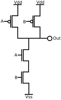
CMOS NAND gate
Logic gates
Using only pipes and our small MOSFET program, we should be able to construct arbitrarily complex digital circuits. Let's start with a simple NAND gate, here in the form of a shell script:
nand.sh
#!/bin/sh

# Usage: nand.sh A B Out

A=$1
B=$2
OUT=$3

VDD=/dev/null
VSS=/dev/zero

./mosfet <$OUT -$A >$VDD &
./mosfet <$OUT -$B >$VDD &

./mosfet <$VSS $B | ./mosfet $A >$OUT
We can test it by creating three named pipes, connecting them manually to Vss or Vdd using cat(1), which behaves like a diode, and connecting the output to something that acts like a buzzer or LED:
$ mkfifo a b q
$ cat </dev/zero >a &     # a is low
$ cat <b >/dev/null &     # b is high
$ ./nand.sh a b q &
$ tr '\000' '\a' <q       # q should be high => no bell
$ mkfifo a b q
$ cat <a >/dev/null &     # a is high
$ cat <b >/dev/null &     # b is high
$ ./nand.sh a b q &
$ tr '\000' '\a' <q       # q should be low => bell
You'll want to do killall mosfet after each run.
Note that we use tr(1) such that it will continuously ring or flash (depending on whether the terminal has an audible or visible bell) when the output q is low, that is, when both a and b are connected to /dev/null.
Control panel
This is clearly not practical for large designs, so we could benefit from some kind of control panel program with buttons and indicators: panel.c
You don't have to read the code, it's pretty straightforward. But download it and try it out! Each argument corresponds to a named pipe which is treated like a button when prefixed with a dash, and like an indicator otherwise.
This is what it looks like for the NAND scenario:
$ ./nand.sh a b out &
$ ./panel -a -b out
[a] b (out)
The inverted out indicates that out is currently high. By moving the cursor (the [ ] brackets) you can select any button and toggle its value using the space key. Press q to quit the program. Don't forget to kill all mosfet processes when you're done.
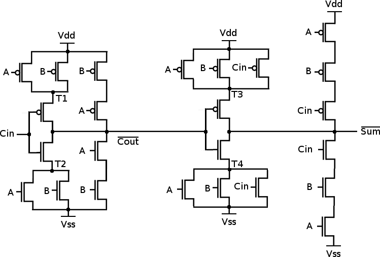
CMOS Mirror Adder
Adding integers
The next step is to implement a full adder (a 1-bit adder with carry in and carry out). Now, of course, every combinational function can be realised using NAND gates, but that's not very transistor efficient. This is how a typical CMOS full adder is constructed:
fa.sh
#!/bin/sh

# Usage: fa.sh A B Cin Cout Sum

A=$1
B=$2
CIN=$3
COUT=$4
SUM=$5

T1=tmp.fa.t1.$$
T2=tmp.fa.t2.$$
T3=tmp.fa.t3.$$
T4=tmp.fa.t4.$$
NCOUT=tmp.fa.ncout.$$
NSUM=tmp.fa.nsum.$$

VSS=/dev/zero
VDD=/dev/null

rm -f $T1 $T2 $T3 $T4 $NCOUT $NSUM
mkfifo $T1 $T2 $T3 $T4 $NCOUT $NSUM

# Mirror Adder

./mosfet <$T1 -$A >$VDD &
./mosfet <$T1 -$B >$VDD &
./mosfet <$NCOUT -$CIN >$T1 &
./mosfet <$NCOUT -$A | ./mosfet -$B >$VDD &

./mosfet <$VSS $A >$T2 &
./mosfet <$VSS $B >$T2 &
./mosfet <$T2 $CIN >$NCOUT &
./mosfet <$VSS $B | ./mosfet $A >$NCOUT &

./mosfet <$T3 -$A >$VDD &
./mosfet <$T3 -$B >$VDD &
./mosfet <$T3 -$CIN >$VDD &
./mosfet <$NSUM -$NCOUT >$T3 &
./mosfet <$NSUM -$CIN | ./mosfet -$B | ./mosfet -$A >$VDD &

./mosfet <$VSS $A >$T4 &
./mosfet <$VSS $B >$T4 &
./mosfet <$VSS $CIN >$T4 &
./mosfet <$T4 $NCOUT >$NSUM &
./mosfet <$VSS $A | ./mosfet $B | ./mosfet $CIN >$NSUM &

# Invert outputs

./mosfet <$VSS $NCOUT >$COUT &
./mosfet <$COUT -$NCOUT >$VDD &

./mosfet <$VSS $NSUM >$SUM &
exec ./mosfet <$SUM -$NSUM >$VDD
Note how temporary fifos are created (T1, T2, T3, T4) with unique suffixes based on the current process ID (the special variable $$ expands to the PID of the shell).
Now we can cascade four full adders into a 4-bit adder and play with it using the control panel:
add4.sh
#!/bin/sh

FIFOS="a3 a2 a1 a0 b3 b2 b1 b0 c3 c2 c1 c0 s4 s3 s2 s1 s0"

rm -f $FIFOS
mkfifo $FIFOS

cat </dev/zero >c0 &
./fa.sh a0 b0 c0 c1 s0 &
./fa.sh a1 b1 c1 c2 s1 &
./fa.sh a2 b2 c2 c3 s2 &
./fa.sh a3 b3 c3 s4 s3 &

./panel -a3 -a2 -a1 -a0 -b3 -b2 -b1 -b0 s4 s3 s2 s1 s0

killall mosfet
rm -f $FIFOS tmp.*
The reason for having a c0 pipe which is connected to the electron supply via cat, rather than just using /dev/zero directly, is that our MOSFET program only works if the gate input is a proper pipe. That's because /dev/zero actually allows you to write data into it, just like /dev/null, so if we hook it up directly to a gate, it's going to behave like an undefined signal.
This is what the 4-bit adder setup looks like when calculating the sum of five and seven:
Twelve looks about right. Clearly, we're approaching something useful here.
Where is the information?
Let's pause for a moment and consider which role the pipes play in this system. They form some kind of network fabric that allows our MOSFET instances to communicate, and yet the information being communicated is not transmitted through the pipes, because the pipes just provide an infinite series of completely predictable null-bytes. In contrast, the actual information is transmitted through the flow control mechanism of the pipes. This is akin to modulated carrier waves such as a brief brake that propagates backwards through a line of moving cars on a road.
What's fascinating about this, is that flow control information can travel across a pipe in either direction. The null-bytes always travel from the writing end to the reading end, but just as the writer may signal the reader by filling an empty pipe, the reader may signal the writer by draining a full pipe. The communication is half-duplex however, because the reader and the writer would get in each other's way if they tried to do this simultaneously.
Registers
One critical building block is still missing. Combinational logic is all very well, but large digital designs tend to consist of a number of interconnected state machines. In order to build state machines, we need to be able to keep track of the current state as bits in some kind of memory.
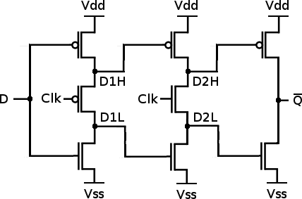
Positive edge triggered flip flop
A convenient type of memory is the D-flip flop. It can be implemented in a number of ways, and we'll go for a variant that uses TSPC (true single-phase clocked) logic. This design is interesting because it relies on the parasitic capacitance of the wires, so when used in a real integrated circuit it requires a minimum clock frequency to work, otherwise the bits stored in the registers become corrupt through leakage currents. Our pipe capacitors are ideal in the sense that there's no leakage at all. The buffers hold their contents until the pipe is destroyed.
flipflop.sh
#!/bin/sh

# Usage: flipflop.sh Clk D Q

CLK=$1
D=$2
Q=$3

D1H=tmp.ff.d1h.$$
D1L=tmp.ff.d1l.$$
D2H=tmp.ff.d2h.$$
D2L=tmp.ff.d2l.$$
NQ=tmp.ff.nq.$$

VSS=/dev/zero
VDD=/dev/null

FIFOS="$D1H $D1L $D2H $D2L $NQ"
rm -f $FIFOS
mkfifo $FIFOS

./mosfet <$VSS $D >$D1L &
./mosfet <$D1L -$CLK >$D1H &
./mosfet <$D1H -$D >$VDD &

./mosfet <$VSS $D1L >$D2L &
./mosfet <$D2L $CLK >$D2H &
./mosfet <$D2H -$D1H >$VDD &

./mosfet <$VSS $D2L >$NQ &
./mosfet <$NQ -$D2H >$VDD &

./mosfet <$VSS $NQ >$Q &
exec ./mosfet <$Q -$NQ >$VDD
Like we did with the full adder, we'll tack on an inverter at the end in order to get the same polarity at the output and input; in a real design, we'd just as often want the output signal inverted, in which case the extra inverter is unnecessary, which is why it's not considered to be a canonical part of the flip flop.
The operation of this flip flop is quite elegant. Suppose Clk is low, so that the first stage becomes a regular inverter. Then, D1H = D1L = /D. The last stage is also an inverter, so let's assume we have D2H = D2L = Q. These two stages are separated by an inverter that has been split into two halves by the second clocking transistor. Suppose D ≠ Q, so that D1H = D1L = D2H = D2L, which would not be possible if the split inverter were a regular inverter. The upper half of the split inverter can only pull D2H to a high level, but D2H affects a transistor in the final stage which only turns on when provided with a low gate voltage. Conversely, the lower half of the split inverter can only pull D2L to a low level, but D2L affects a transistor which only turns on in response to a high gate voltage. The upshot of this is that /Q might be disconnected from whatever power rail was driving it, but as long as there is no leakage current, it retains its previous voltage. When the clock toggles, a similar phenomenon takes place in the left half of the circuit, while the right half behaves like a regular inverter, and the value of D propagates one step to the right.
Note that the register will power up in an unknown state, possibly a metastable one. It must be cleared by explicitly clocking in a logic zero.
Putting it all together
Now we should be able to construct a working state machine. To keep it simple, we'll transform the 4-bit adder into a 4-bit accumulating machine. The current state is kept in a 4-bit register, its value represented by (q3, q2, q1, q0). The next state is calculated by adding a user-supplied 4-bit number to the current state. At every positive clock edge, the flip flops shift in the new bits provided by the adder, causing a state transition to take place.
counter.sh
#!/bin/sh

FIFOS="clk a3 a2 a1 a0 c4 c3 c2 c1 c0 d3 d2 d1 d0 q3 q2 q1 q0"

rm -f $FIFOS
mkfifo $FIFOS

cat </dev/zero >c0 &
./fa.sh a0 q0 c0 c1 d0 &
./fa.sh a1 q1 c1 c2 d1 &
./fa.sh a2 q2 c2 c3 d2 &
./fa.sh a3 q3 c3 c4 d3 &

./flipflop.sh clk d0 q0 &
./flipflop.sh clk d1 q1 &
./flipflop.sh clk d2 q2 &
./flipflop.sh clk d3 q3 &

./panel -a3 -a2 -a1 -a0 -clk q3 q2 q1 q0

killall mosfet
rm -f $FIFOS tmp.*
And if you try it, you'll find that it runs like clockwork.
Conclusion
So there it is. We've been able to construct gates and flip flops using nothing but UNIX pipes and our small MOSFET tool. We may now proceed to design any digital circuits we want: Processors, memories, entire computers... The world is ours to conquer!
As long as we don't run out of PIDs.
Some images courtesy of wikimedia commons: [1] [2] [3] This article is published under the Creative Commons Attribution-Share Alike license.
![[1]](http://en.wikipedia.org/wiki/File:IGFET_N-Ch_Enh_Labelled_simplified.svg)
![[2]](http://en.wikipedia.org/wiki/File:IGFET_P-Ch_Enh_Labelled_simplified.svg)
![[3]](http://en.wikipedia.org/wiki/File:CMOS_NAND.svg)
Posted Tuesday 2-Aug-2011 09:48
Discuss this page
Disclaimer: I am not responsible for what people (other than myself) write in the forums. Please report any abuse, such as insults, slander, spam and illegal material, and I will take appropriate actions. Don't feed the trolls.
Jag tar inget ansvar för det som skrivs i forumet, förutom mina egna inlägg. Vänligen rapportera alla inlägg som bryter mot reglerna, så ska jag se vad jag kan göra. Som regelbrott räknas till exempel förolämpningar, förtal, spam och olagligt material. Mata inte trålarna.
Tue 2-Aug-2011 12:11
21 more comments hidden. Click to show all.
Wed 11-Jul-2012 14:25
Mon 28-May-2018 17:30
Regards,
Raphael
Mon 28-May-2018 17:30
Regards,
Raphael
Wed 1-Aug-2018 18:55