


The Multiplexius plushie is available to order!
Limited edition! Last day to order is February 13.


Front-Panel Booting an ATmega88 Microcontroller
Your computer contains both hardware and software. Even if you buy a PC motherboard separately, there's software (called BIOS) in one of the chips, otherwise nothing would happen when you turn on the power. That chip was programmed in a factory by a computer-controlled system, and that computer-controlled system also came with software, perhaps in a boot ROM. That boot ROM was again programmed by a computer, or manufactured from a blueprint that was generated on a computer.
But if you keep tracing this lineage backwards in time, you eventually reach a point of deus-ex-machina: A bootstrap routine that was programmed by hand, by a human being, most likely on the front panel of a minicomputer.
I wanted to experience that process first hand. There are minicomputer emulators, of course, but they cannot serve this particular purpose: With an emulator you're not bringing software to hardware, you're bringing software to some other software that's already up and running.
Besides, I wanted to do this on a computer that meant something to me personally, a computer from my own lifetime. So I was delighted to realise that the good old ATmega88 just happens to have a front-panel-compatible programming interface!
Presentation video
This video starts with a brief tour of minicomputers and front panels in general, and goes on to explain how I constructed my own front panel for the ATmega88. It culminates with me using it to enter a small program to blink some LEDs: Computer hardware, delivered without software, and brought to life for the first time by hand.
I collected photographs and music from a number of sources, most notably Wikimedia Commons. You can read the full credits here.
The historical narrative is simplified for brevity. For a more thorough account, I can highly recommend the Wikipedia article on Booting.
Schematics and gotchas
This is how I wired up the front-panel:
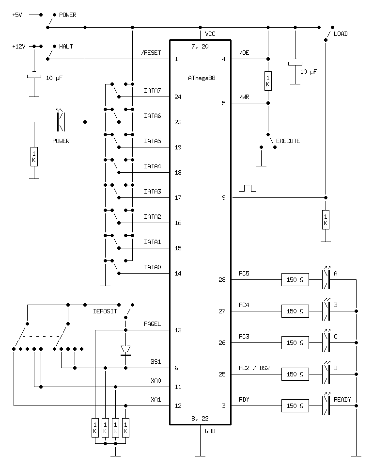
The rotary switch has two independent poles, and each of them is used to connect Vcc to a normally pulled-down input on the microcontroller. I used a rotary switch with six positions that could be reconfigured to five positions by inserting a plastic stop.
As you can see in the schematics, the five orange LEDs are connected in series with 150 Ω resistors, but I used 1 kΩ for the red Power LED (all LEDs appear to have the same colour in the video, but that's because they are overexposed). Obviously you should calculate the appropriate resistor values for your particular LEDs, but in my case 150 Ω would have worked for the red LED as well. However, it was much brighter than the others, so I tamed it with a larger resistance to get a consistent look.
One issue took me a while to figure out: The contents of the Command register appear to have subtle effects on the microcontroller even before you execute the command. I suspect that it controls power domains and/or internal clocks of the chip. Specifically, the Write Flash bit needs to be enabled in the Command register in order for the page buffer to work. I evade this point in the video in order to keep things brief, but in case you wish to build a similar front panel yourself you should be aware of it.
Limitations and future work
My interface doesn't expose the full functionality of the parallel programming interface. In particular, it doesn't provide a way to inspect memory contents. It would be possible to wire up eight LEDs above the switches, and figure out a way to interact safely with the bidirectional data bus. In my design, the switches force the lines to Vcc or ground with no protection at all. The output-enable signal is permanently tied high, so everything is fine in programming mode, but if you toggle in some software that configures one of these pins as an output you are likely to short-circuit the system.
Note the diode (I used a 1N4148) between PAGEL and BS1. According to the description of the parallel programming interface in the datasheet, BS1 must be high when you deposit an instruction word to the page buffer. BS1 is normally used to distinguish between the high and low bytes of the address and data registers, so you'd have to point the rotary switch to Address High or Data High every time you wanted to press Deposit. The diode eliminates this problem.
That is an example of putting logic (hardware logic, mind!) in the panel to hide or abstract some detail of the programming interface. This idea could be taken further. For instance, you could replace the rotary switch with five separate Load buttons, one for each register. That would require generating a two-step signal: First configure the target register, then activate the trigger (the /WR signal). But this is easily done with TTL or CMOS logic chips. You could also add logic chips for a separate address counter, with dedicated LEDs and buttons for loading the counter from the switches, incrementing it, and sending it to the Address Low register of the microcontroller.
All in all, though, I am happy with my minimalistic approach. I wasn't planning to use the front panel extensively because, as mentioned in the video, front-panel booting is not a practical way to start a computer. But it sure is beautiful.
Posted Friday 24-Oct-2025 06:51
Discuss this page
Disclaimer: I am not responsible for what people (other than myself) write in the forums. Please report any abuse, such as insults, slander, spam and illegal material, and I will take appropriate actions. Don't feed the trolls.
Jag tar inget ansvar för det som skrivs i forumet, förutom mina egna inlägg. Vänligen rapportera alla inlägg som bryter mot reglerna, så ska jag se vad jag kan göra. Som regelbrott räknas till exempel förolämpningar, förtal, spam och olagligt material. Mata inte trålarna.
Fri 24-Oct-2025 20:05
Tue 28-Oct-2025 20:20
Wed 29-Oct-2025 07:17
That's because he's directly controlling the programming interface here, the panel isn't a memory monitor like the old mini-computers used. The "load" label is already used for loading the command and parameter bytes. Writing bytes to memory needed a second button and a distinct label, hence a synonym was used.
Wed 29-Oct-2025 08:07
PDP-8 and PDP-11 front panels have a "deposit" button to write a word to memory.
Wed 29-Oct-2025 13:13
LEDs next to the data switches. A 100 ohm resistor and an LED between the data lines. And 10 kohms next to the LED legs. Then the switch's up/down pull works through 100 ohm + 10 kohm and when the switch is down, the LED lights up if the controller is controlling data.
Otherwise, there are enough ports on the top edge for more leds. As an extra, you could maybe even use an external IO port from the ones that are left.